
- Optical Transceivers
- SFP+ Transceivers
- XENPAK Transceivers
- XFP Transceivers
- X2 Transceivers
- SFP Transceivers
- Compatible SFP
- 3Com SFP
- Alcatel-Lucent SFP
- Allied Telesis SFP
- Avaya SFP
- Brocade SFP
- Cisco SFP
- D-Link SFP
- Dell SFP
- Enterasys SFP
- Extreme SFP
- Force10 SFP
- Foundry SFP
- H3C SFP
- HP SFP
- Huawei SFP
- Intel SFP
- Juniper SFP
- Linksys SFP
- Marconi SFP
- McAfee SFP
- Netgear SFP
- Nortel SFP
- Planet SFP
- Q-logic SFP
- Redback SFP
- SMC SFP
- SUN SFP
- TRENDnet SFP
- ZYXEL SFP
- Other SFP
- FE SFP
- GE SFP
- OC3 SFP
- OC12 SFP
- OC48 SFP
- Copper SFP
- CWDM SFP
- DWDM SFP
- BIDI SFP
- Fiber Channel SFP
- Multi-Rate SFP
- SGMII SFP
- Compatible SFP
- GBIC Transceivers
- Passive Components
- Networking
- Cables
- Equipments
- Tools
- Special Offers
Brands

Industry News

Fiber Optic Wiki

Fiber Optic Wiki
RTU in RFTSs and Full-feature OTDR
August 5, 2011The equipment is summarized below, and detailed in GR-196, Generic Requirements for Optical Time Domain Reflectometer (OTDR) Type Equipment.
Multiple devices on a cable
August 4, 2011If two devices attach to a single cable, one must be designated as device 0 (commonly referred to as master) and the other as device 1 (slave). This distinction is necessary to allow both drives to share the cable without conflict. The master drive is the drive that usually appears "first" to the computer's BIOS and/or operating system. On old BIOSes (Intel 486 era and older), the drives are often referred to by the BIOS as "C" for the master and "D" for the slave following the way DOS would refer to the active primary partitions on each.
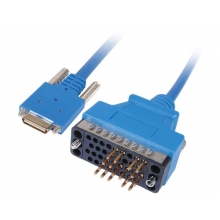
Differences between connectors on 80-conductor cables
August 4, 2011The image shows PATA connectors after removal of strain relief, cover, and cable. Pin one is at bottom left of the connectors, pin 2 is top left, etc., except that the lower image of the blue connector shows the view from the opposite side, and pin one is at top right.
Parallel ATA interface
August 4, 2011
Parallel ATA cables transfer data 16 bits at a time. The traditional cable uses 40-pin connectors attached to a ribbon cable. Each cable has two or three connectors, one of which plugs into an adapter interfacing with the rest of the computer system. The remaining connector(s) plug into drives.
Obsolescence of ATA
August 4, 2011For a long period of time, ATA ruled as the primary storage device interface and in some systems a third and fourth motherboard interface was provided (for example, Promise Ultra-100), for up to eight ATA devices attached to the motherboard.
Interface size limitations
August 4, 2011Due to lack of foresight the first drive interface used 22-bit addressing mode which resulted in a maximum drive capacity of 2 GByte. Later the first formalized ATA specification used a 28-bit addressing mode, allowing for the addressing of 228 268 435 456 sectors (blocks) of 512 bytes each, resulting in a maximum capacity of 128 GiB (137 GB).
Featured


Bestsellers


Registered Names and Trademarks are the copyright and property of their respective owners.
Copyright © 2026 Fiberise(A company of Cablexa Ltd). All rights reserved.
Copyright © 2026 Fiberise(A company of Cablexa Ltd). All rights reserved.