
- Optical Transceivers
- SFP+ Transceivers
- XENPAK Transceivers
- XFP Transceivers
- X2 Transceivers
- SFP Transceivers
- Compatible SFP
- 3Com SFP
- Alcatel-Lucent SFP
- Allied Telesis SFP
- Avaya SFP
- Brocade SFP
- Cisco SFP
- D-Link SFP
- Dell SFP
- Enterasys SFP
- Extreme SFP
- Force10 SFP
- Foundry SFP
- H3C SFP
- HP SFP
- Huawei SFP
- Intel SFP
- Juniper SFP
- Linksys SFP
- Marconi SFP
- McAfee SFP
- Netgear SFP
- Nortel SFP
- Planet SFP
- Q-logic SFP
- Redback SFP
- SMC SFP
- SUN SFP
- TRENDnet SFP
- ZYXEL SFP
- Other SFP
- FE SFP
- GE SFP
- OC3 SFP
- OC12 SFP
- OC48 SFP
- Copper SFP
- CWDM SFP
- DWDM SFP
- BIDI SFP
- Fiber Channel SFP
- Multi-Rate SFP
- SGMII SFP
- Compatible SFP
- GBIC Transceivers
- Passive Components
- Networking
- Cables
- Equipments
- Tools
- Special Offers
Brands

Industry News

Fiber Optic Wiki

Fiber Optic Wiki
What is Light scattering?
May 2, 2012The propagation of light through the core of an optical fiber is based on total internal reflection of the lightwave. Rough and irregular surfaces, even at the molecular level, can cause light rays to be reflected in random directions. This is called diffuse reflection or scattering, and it is typically characterized by wide variety of reflection angles.
What is Termination and splicing?
May 2, 2012Optical fibers are connected to terminal equipment by optical fiber connectors. These connectors are usually of a standard type such as FC, SC, ST, LC, MTRJ, or SMA, which is designated for higher power transmission.
What are Fiber Optic Connector Types?
May 1, 2012
Connector Termination Styles
1.Epoxy/Polish Connectors
2.Anaerobic Adhesive/Polish Connectors
3.UV Adhesive/Polish Connectors
4.Crimp/Polish Connectors
5.Quick Termination (Pre-Terminated) Connectors
What is Fiber Optic Gigabit Ethernet ?
May 1, 2012Fiber implementations of Gigabit Ethernet is specified in IEEE 802.3z and IEEE 802.3ab defines the common twisted-pair copper 1000BASE-T interface type. Gigabit Ethernet is also refered to as 1000Base-X. The "X" signifies a physical layer based on the ANSI X3.230 Fibre Channel standard.
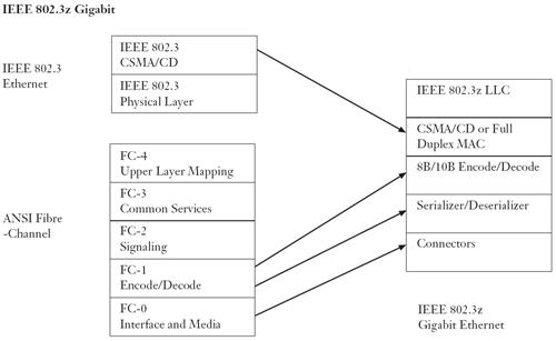
The IEEE 802.3z standard includes 1000BASE-SX transmission over multi-mode fiber, 1000BASE-LX transmission over single-mode fiber, and the nearly obsolete 1000BASE-CX for transmission over balanced copper cabling. These standards use 8B/10B encoding, inflating the line rate by 25%, from 1000 Mbit/s to 1250 Mbit/s. The symbols are then sent using NRZ, as 8B/10B mapping already handles the DC balancing properties of the signal (compare to 1000BASE-T).
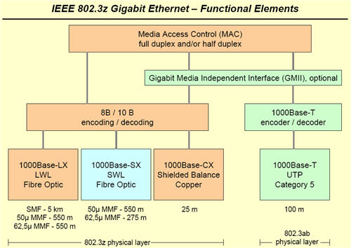
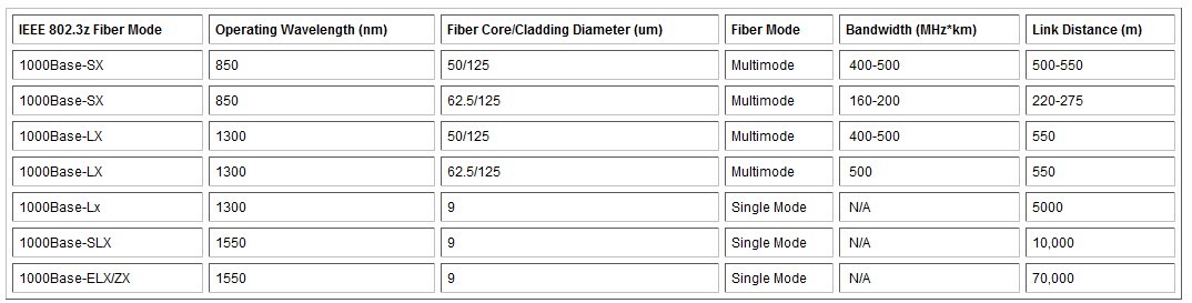
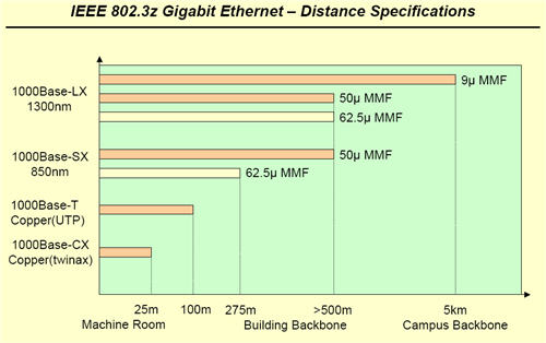
1000BASE-SX
1000BASE-SX is a fiber optic gigabit Ethernet standard. It operates over multi-mode fiber using a 850 nanometer, near infrared (NIR) light wavelength. The standard specifies a distance capability between endpoints of 220 m over 62.5/125 µm fibre although in practice, with good quality fibre and terminations, 1000BASE-SX will usually work over significantly longer distances. Modern 50/125 µm fibres can reliably extend the signal to 500 m or more. This standard is highly popular for intra-building links in large office buildings, colocation facilities and carrier neutral internet exchanges. Typical optical power parameters of SX interface: maximum mean output power = -5 dBm; stressed receiver sensitivity = -14 dBm.
1000BASE-LX
1000BASE-LX is a fiber optic gigabit Ethernet standard, using a long wavelength laser (See IEEE 802.3 Clause 38). Signaling speed 1.25±100 ppm GBd, wavelength 1270 to 1355 nm, RMS spectral width (max) 4 nm. Typically, GbE lasers will be specified as having a 1300 or 1310 nm wavelength.
1000BASE-LX is specified to work over a distance of up to 2 km over 9 µm single-mode fiber. In practice it will often operate correctly over a much greater distance. Many manufacturers will guarantee operation up to 10 or 20 km, provided that their equipment is used at both ends of the link. 1000BASE-LX can also run over multi-mode fiber with a maximum segment length of 550 m. For any link distance greater than 300 m, the use of a special launch conditioning patchcord may be required. This launches the laser at a precise offset from the center of the fiber which causes it to spread across the diameter of the fiber core, reducing the effect known as differential mode delay which occurs when the laser couples onto only a small number of available modes in multi-mode fiber.
1000BASE-ZX and 1000BASE-LH
1000BASE-ZX and 1000BASE-LH are non-standard but industry accepted terms to refer to gigabit Ethernet transmission using 1550 nm wavelength to achieve distances of at least 70 km over single-mode fiber.
Classify fiber optic transceiver
May 1, 2012
Optical properties by Category:
By optical fiber to points, can be divided into multi-mode fiber transceiver and single-mode fiber transceiver.
Single-mode fiber transceiver: transmission distance of 20-120 km
What is Fiber optic sensors?
May 1, 2012Fibers have many uses in remote sensing. In some applications, the sensor is itself an optical fiber. In other cases, fiber is used to connect a non-fiberoptic sensor to a measurement system. Depending on the application, fiber may be used because of its small size, or the fact that no electrical power is needed at the remote location, or because many sensors can be multiplexed along the length of a fiber by using different wavelengths of light for each sensor, or by sensing the time delay as light passes along the fiber through each sensor. Time delay can be determined using a device such as an optical time-domain reflectometer.
Featured


Bestsellers


Registered Names and Trademarks are the copyright and property of their respective owners.
Copyright © 2026 Fiberise(A company of Cablexa Ltd). All rights reserved.
Copyright © 2026 Fiberise(A company of Cablexa Ltd). All rights reserved.