

- Optical Transceivers
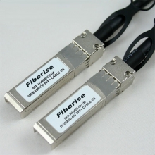
- SFP+ Transceivers
- XENPAK Transceivers
- XFP Transceivers
- X2 Transceivers
- SFP Transceivers
- Compatible SFP
- 3Com SFP
- Alcatel-Lucent SFP
- Allied Telesis SFP
- Avaya SFP
- Brocade SFP
- Cisco SFP
- D-Link SFP
- Dell SFP
- Enterasys SFP
- Extreme SFP
- Force10 SFP
- Foundry SFP
- H3C SFP
- HP SFP
- Huawei SFP
- Intel SFP
- Juniper SFP
- Linksys SFP
- Marconi SFP
- McAfee SFP
- Netgear SFP
- Nortel SFP
- Planet SFP
- Q-logic SFP
- Redback SFP
- SMC SFP
- SUN SFP
- TRENDnet SFP
- ZYXEL SFP
- Other SFP
- FE SFP
- GE SFP
- OC3 SFP
- OC12 SFP
- OC48 SFP
- Copper SFP
- CWDM SFP
- DWDM SFP
- BIDI SFP
- Fiber Channel SFP
- Multi-Rate SFP
- SGMII SFP
- Compatible SFP
- GBIC Transceivers
- Passive Components
- Networking
- Cables
- Equipments
- Tools
- Special Offers
Brands

Industry News

Fiber Optic Wiki

How OTDRs Work
Unlike sources and power meters which measure the loss of the fiber optic cable plant directly, the OTDR works indirectly. The source and meter duplicate the transmitter and receiver of the fiber optic transmission link, so the measurement correlates well with actual system loss.
The OTDR, however, uses backscattered light of the fiber to imply loss. The OTDR works like RADAR, sending a high power laser light pulse down the fiber and looking for return signals from backscattered light in the fiber itself or reflected light from connector or splice interfaces.
At any point in time, the light the OTDR sees is the light scattered from the pulse passing through a region of the fiber. Only a small amount of light is scattered back toward the OTDR, but with wider test pulses, sensitive receivers and signal averaging, it is possible to make measurements over relatively long distances. Since it is possible to calibrate the speed of the pulse as it passes down the fiber, the OTDR can measure time, calculate the pulse position in the fiber and correlate what it sees in backscattered light with an actual location in the fiber. Thus it can create a display of the amount of backscattered light at any point in the fiber.
Since the pulse is attenuated in the fiber as it passes along the fiber and suffers loss in connectors and splices, the amount of power in the test pulse decreases as it passes along the fiber in the cable plant under test. Thus the portion of the light being backscattered will be reduced accordingly, producing a picture of the actual loss occurring in the fiber. Some calculations are necessary to convert this information into a display, since the process occurs twice, once going out from the OTDR and once on the return path from the scattering at the test pulse.
December 22, 2011
Featured


Bestsellers


Registered Names and Trademarks are the copyright and property of their respective owners.
Copyright © 2026 Fiberise(A company of Cablexa Ltd). All rights reserved.
Copyright © 2026 Fiberise(A company of Cablexa Ltd). All rights reserved.
