
- Optical Transceivers
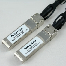
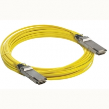
- SFP+ Transceivers
- XENPAK Transceivers
- XFP Transceivers
- X2 Transceivers
- SFP Transceivers
- Compatible SFP
- 3Com SFP
- Alcatel-Lucent SFP
- Allied Telesis SFP
- Avaya SFP
- Brocade SFP
- Cisco SFP
- D-Link SFP
- Dell SFP
- Enterasys SFP
- Extreme SFP
- Force10 SFP
- Foundry SFP
- H3C SFP
- HP SFP
- Huawei SFP
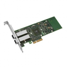
- Intel SFP
- Juniper SFP
- Linksys SFP
- Marconi SFP
- McAfee SFP
- Netgear SFP
- Nortel SFP
- Planet SFP
- Q-logic SFP
- Redback SFP
- SMC SFP
- SUN SFP
- TRENDnet SFP
- ZYXEL SFP
- Other SFP
- FE SFP
- GE SFP
- OC3 SFP
- OC12 SFP
- OC48 SFP
- Copper SFP
- CWDM SFP
- DWDM SFP
- BIDI SFP
- Fiber Channel SFP
- Multi-Rate SFP
- SGMII SFP
- Compatible SFP
- GBIC Transceivers
- Passive Components
- Networking
- Cables
- Equipments
- Tools
- Special Offers
Brands

Industry News

Fiber Optic Wiki

Fibre Channel signal characteristics
Fibre channel electrical signals are sent over a duplex differential interface. This usually consists of twisted-pair cables with a nominal impedance of 75 ohms (single-ended) or 150 ohms (differential). This is a genuine differential signalling system so no ground reference is carried through the cable, except for the shield. Signalling is AC-coupled, with the series capacitors located at the transmitter end of the link.
The definition of the Fibre Channel signalling voltage is complex. Eye-diagrams are defined for both the transmitter and receiver. There are many eye-diagram parameters which must all be met to be compliant with the standard. In simple terms, the transmitter circuit must output a signal with a minimum of 600 mV peak-to-peak differential, maximum 2000 mV peak-to-peak differential. A good signal looks rather like a sine-wave with a fundamental frequency of half the data rate, so 1 GHz for a typical system running at 2 gigabits per second.
The Bit-Error Rate (BER) objective for Fibre Channel systems is 1 in 1012 (1 bit in 1,000,000,000,000 bits). At 2 Gbit/s this equates to seven errors per hour. Therefore, this is a common event and the receiver circuitry must contain error-handling logic. In order to achieve such a low error-rate, jitter "budgets" are defined for the transmitter and cables.
June 30, 2011
Featured


Bestsellers


Registered Names and Trademarks are the copyright and property of their respective owners.
Copyright © 2026 Fiberise(A company of Cablexa Ltd). All rights reserved.
Copyright © 2026 Fiberise(A company of Cablexa Ltd). All rights reserved.